CAD CAM - Understanding the Basics: A Review
Savitha P.N
Affiliation
- 1Specialist Prosthodontist, Private dental practice, Dubai
- 2Senior Lecturer, Department of Prosthodontics, Bangalore Institute of Dental Sciences, Bangalore
Corresponding Author
Smitha Annie Jacob, Specialist Prosthodontist, Private dental practice, Dubai E-mail: dr.smitha.jacob@gmail.com
Citation
Smitha A.J., et al. CAD CAM- Understanding the Basics: A Review. (2016) J Dent Oral Care 2(3): 1- 6.
Copy rights
© 2016 Smitha A.J. This is an Open access article distributed under the terms of Creative Commons Attribution 4.0 International License.
Keywords
CAD CAM; Ceramics; Digital Dentistry; Digital Workflow; CEREC
Abstract
CAD/CAM is a field of dentistry and prosthodontics using CAD/CAM (computer-aided design and computer-aided manufacturing) to improve the design and creation of dental restorations, especially dental prostheses, including crowns, crown, veneers, inlays and onlays, fixed bridges, dental implant restorations, dentures (removable or fixed), and orthodontic appliances.
There exists a misconception that the CAD/CAM process is complicated and time-consuming. However, the CAD/CAM system is simple to operate, versatile, and precise. All-ceramic restorations can be designed and milled chair side, with the added advantage of elimination of traditional impressions and temporaries, and the patient leaves the appointment in about an hour with the final restoration in place. Dental CAD/CAM is approaching 20 years of clinical experience and has a proven track record on all relevant aspects of clinical performance, including fit, longevity and survival rates, sensitivity, strength, and wear.
Introduction
Aim
The application of dental CAD/CAM systems is promising, not only in the field of crowns and FPDs, but also in other fields of dentistry. There is no doubt that the application of CAD/CAM technology in dentistry provides innovative, state-of-art dental service, and contributes to the health and Quality of Living (QOL) of patients. The purpose of this paper is to give an in-depth knowledge of CAD CAM technology to the readers as today’s dentistry has entered into the digital era.
The term CAD/CAM, which comes from machine-tool technology and stands for “Computer-Aided-Design / Computer- Aided-Manufacturing”, designates the three-dimensional planning of a work piece on the screen of a computer with subsequent automated production by a computer controlled machine tool[1,2]. In 1971, Francois Duret introduced CAD-CAM technology to the field of dentistry. His idea was based upon the assumption that the technologies established in industry could be easily transferred to dentistry.
Though casting procedure has advanced over the past years, each of its steps could induce error in the final casting. Until 1988, indirect ceramic dental restorations were fabricated by conventional methods (sintering, casting and pressing) and neither was pore-free. Machining blocks of pore-free industrial quality ceramic can alternately produce pore-free restorations[3-5]. The tremendous advances in computers and robotics could also be applied to revolutionize dentistry and provide both precision and reduce time consumption. With the combination of optoelectronics, computer techniques and sinter technology, computerized dentistry has paved the way for a new generation dental ceramic with an unprecedented high strength and durability, derived from developments in Nano-ceramic technologies in the last decades.
What is CAD CAM?
The contemporary CAD/CAM systems consist of three components:
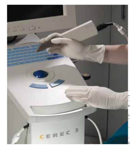
1. The scanner, which scans the dental preparation provided by the dentist either intra-orally or extra-orally by reference to tooth models (Figure 1). For inlays and single crown frameworks, just the surface data of the prepared teeth need to be digitized. For FPD frameworks or additional occlusal characterization, further data from the neighboring teeth and antagonists, as well as from the spatial relation of the prepared teeth to one another, are required[6-9].
Figure 1: CEREC Scanner.
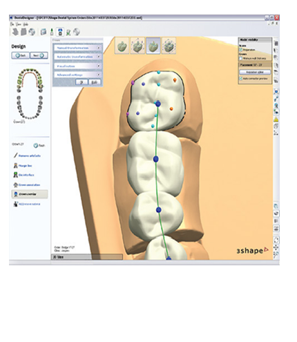
2. The software CAD consists of a computer unit used for the three-dimensional planning and design of restorations on the computer screen (Figure 2). The software programs available today offer a high level of intervention and permit the design and production of an individually adapted restoration. Systems not offering a full CAD component are not considered as CAD/CAM systems but just as CAM systems[10].
Figure 2: Software dental designer.
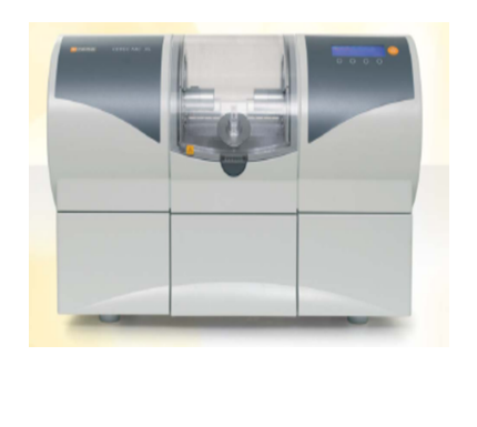
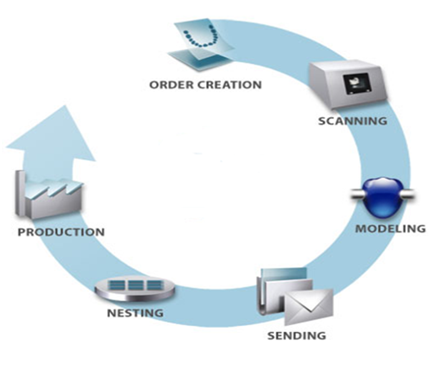
3. The hardware CAM covers different production technologies for converting the virtual restoration into a dental material (Figure 3). At present, computer-controlled milling or grinding machines are mainly used. They machine the restoration from the full material block consisting of prefabricated metal or ceramic[11,12]. As a rule, after the CAM production, some manual corrections and final polishing or individualization of the restoration with staining colors or veneering materials are required to be carried out by the dental technician (Figure 4).
Figure 3: Sirona Milling Unit.
Figure 4: Cycle of CAD/CAM.
Scanning of Preparation
Since 1971, a number of attempts to dental CAD/CAM have been reported. The most prominent are:
1. Holodontography by altschuler : A report dated 1971 claims that development of laser holography can significantly influence the procedures used in dental care. It mentions the use of tooth prints recorded by means of a combination of computers and laser holography. Such tooth print could serve for diagnostic and forensic purposes, but also applicable to prosthetic and restorative work[13]. A specific task would be computer-controlled milling of dental crowns based on contour holograms.
2. The Duret/ Hennson/ Sopha system : The origin of French approach dates back to the early seventies. Goal of this endeavor is the computer-aided restoration and dentistry in the broadest sense. The primary application of the system, however, was the fabrication of crowns. The original scanning principle was based on laser holography. Dr François Duret’s method requires a set of different views of the preparation. The individual views are correlated by the computer to produce a three-dimensional record. To facilitate the alignment, the dentist places reference brackets within the field of view. The design is accomplished by manually tracing the cervical margin of the preparation by means of a large screen color monitor and a digitizing tablet[14]. The program uses a selective shrinkage algorithm to produce an optimum cementation gap. The machine is equipped with three axes and has the additional capability to turn the work piece upside down.
3. Active triangulation: This principle does not rely on an image pair as obtained by two-eyed vision. Instead one optical path is converted from receptor to transmitter or, more accurately, a pattern projector. Due to the physical separation of the two channels a certain amount of parallax is introduced. Since the parallax is a known constant, the resulting range-dependent shift of the pattern projected onto the object can be accurately converted into depth values[15].
Data Acquisition
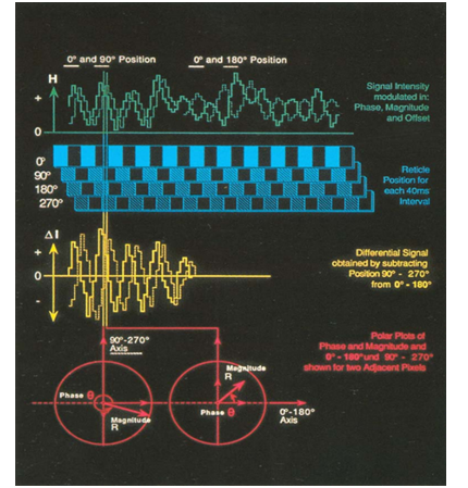
The first element of the data acquisition chain is a solid state image sensor. This device accurately converts light intensity to voltage when read in a line by line mode. The alternating regions of dark and light translate into higher and lower voltages. When reading a sensor line, which runs mesio-distally, sinusoidal pattern is observed[16,17]. While the reticle features a square pattern (bands are either transparent or totally opaque), limited resolution of the detected signal approximates a sine wave. Just like the individual line, every line of the pattern is shifted proportionally to vertical distances. In mathematical terms, the phase of the spatial frequency is modulated.
Once the particular phase which corresponds to a reference level has been established by calibration, the elevation of any point of the object can be calculated from the phase shift. A more careful analysis of the sinusoidal pattern reveals some additional difficulties: the shape of this pattern is not very well behaved. It exhibits large local variations in both amplitude and offset i.e. the distance from the baseline. The latter are caused by the various amounts of stray light and sensor dark current. The former are caused by the fact, that the amount of light picked up by the sensor is a function of the slope of the preparation walls at any point. An additional difficulty arises from the non-uniformity in the response of the individual sensor elements. Due to limitations in the art of semiconductor fabrication, a typical sensor will even contain a certain amount of blind cells. In order to isolate the three variables – phase, magnitude and offset- at least three images are required, all taken with the exact same orientation, but each using a different phase of the projected pattern[18,19].
A sequence of four images (Figure 5), proved to be a more efficient approach in our particular application and hardware implementation. The reticle is physically translated during a period of 4 times 40 milliseconds from an arbitrary 0° initial position over 360°, i.e., one entire line period. For reasons of clarity, the illustration shows a fixed position for each frame, while in reality the pattern is continuously swept across the image. Various levels of intensity, reflecting the actual position of pattern, are detected. The signal is a stepped approximation of the actual intensity pattern since the elements of the sensor have finite dimensions (period of pattern 200μ divided into a 22μ element pitch of the sensor array yields approx. 9 samples per period), while the modulated part of the signal is shifted in phase, the offset, represented by the average intensity, remains constant[20,21]. This observation suggests a differential operation. Subtracting the 180° image from the 0° image cancels the offset portion off the signal. Since this subtraction is achieved by a reaction of modify-write operation in the image memory, it is executed instantaneously. The 90° - 270° subtraction is accomplished in the same way.
Figure 5: Sequence of four images.
At the end of the 160 millisecond exposure, we thus find the two differential data sets in the frame buffer. The characterization features of the modulation have been unaffected by the subtraction, the amplitudes have been doubled and the signals are now biased at the zero level. The 90° phase between the two signals has been preserved. We are now left with a data pair corresponding to each picture cell- or pixel- of the image. Data pairs must be transformed to yield the desired depth information. The two- dimensional array of the depth values is referred to as the profile. A second set of values, representing local contrast amplitude can be obtained from this conversion; in our context we call this second set of data the hill-shaded image[22-24].
Prior to making an optical impression with the sensor, it is necessary to powder the tooth surface and the entire field uniformly. The detection of the pattern cast onto an untreated preparation is not possible for the following reasons: on the one hand the different slopes of the preparation and the differences in surface quality yield a dynamic range of intensities, which is too large to be accommodated by the sensor and the associated circuitry. The steep walls appear as virtually black regions. The cusp which reflect the incident light in a specular fashion tend to glare thereby causing smearing artifacts similar to the human retina when we look directly into a powerful light source[25,26]. On the other hand the dentin and enamel is translucent whereby it absorbs at least partially, the pattern projected onto its surface. To alleviate both problems, the surface of the tooth, and for that matter, the entire field of view must be coated with a thin opaquer layer. A fine coat of titanium dioxide produces a highly uniform scattering of the light. The remaining variation in intensity is very desirable since it enhances the three-dimensional features of the preparation.
Milling of the Ceramic Restoration
The restoration is milled (4 - 7 minutes) with a diamond wheel from a pre manufactured and standardized ceramic block in the milling chamber of the CAM unit. Factory standardized, preformed dental porcelain blocks are homogenous and almost pore - free (Vita Cerec blocks, Dicor Cerec blocks).
The Cam Unit
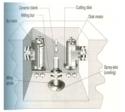
A pump system with an attached water reservoir located at the base of the mobile cart maintains the water pressure required for the hydraulic driven water turbine in the milling chamber. During milling about 5 liters of water is cycled internally, which eliminates the need for external water supply and drainage. The water reservoir system also contains a micro porous filter that traps any of the loosened diamond particles separated from the wheel for future retrieval[27,28] (Figure 6).
Figure 6: The milling unit.
Procedure[29,30]:
• The appropriate ceramic block is selected from a series consisting of different sizes and shade
• The ceramic block is mounted on a metal stub (retainer), inserted into the milling unit and the grinding operation is initiated.
•Grinding of the ceramic restoration is done by a diamond – coated disk / wheel in conjunction with a high velocity water-spray, which simultaneously cools and cleans the milling disk. The restoration is milled from the mesial to the distal proximal surfaces with the block rotating along its central axis and being steadily advanced forward during the milling process. In addition, the diamond wheel not only rotates but also translates up and down over the porcelain block being milled. A series of steps or cuts (200 – 400) are required for milling a ceramic restoration.
The Computer program associated with the milling process has additional interesting features such as[31]:
• Before the milling process, the screen displays the dimensions of the restoration from one proximal surface to the other in 1/900th of an mm.
• During the milling operation, the screen continuously informs the operator of the percentage of completion.
• A continuous readout is displayed concerning the cutting efficiency of the diamond wheel, thereby indicating the probable need for replacement.
Advantages of CAD CAM[32-35]
1. The concept that a dentist can, in a single appointment, administer anesthetic in preparation for, prepare the tooth for, make an impression for, design, mill, customize and place a restoration is desirable for many clinicians and patients. The command of “one-appointment” dentistry is powerful not only for the patient, but also for the entire dental team and the office’s productivity. Single-appointment dentistry has a variety of benefits: the need for only one administration of anesthetic, the absence of need for temporary or provisional restorations (therefore, no lost temporaries or re-cementations), the absence of laboratory fees and a reduction in second-chair set-up costs. These factors ultimately equate to fewer instruments needing to be sterilized, less need for chair time set-up/breakdown and improved office efficiency.
2. Another, often overlooked advantage is the disposable supplies that can be eliminated (from impression material, wax, stone, temporary bridge resin and cement to cotton and paper disposables) by institution of a CAD/CAM system. Clinicians can gain other intangible advantages in the long term by introducing CAD/CAM technology into their already-busy dental practices. With CAD/CAM technology, clinicians maintain total product and artistic control of the restorations to be fabricated and seated. It allows clinicians to spend the majority of their time on tooth preparation and on seating of the final restoration; the software programs’ options deliver a product that may need only endpoint characterization, staining or glazing. The computer and milling processes diminish potential inaccuracies resulting from the hand/laboratory fabrication process and are able to provide a restoration that fits within the 50-micrometer range established by the American Dental Association.
3. When the dentist implements CAD/CAM technology, he or she must create a schedule that supports single-appointment treatment. This schedule arrangement can both save time and increase efficiency. Dentists can complete most CEREC single- unit crowns within one and one-half hours. Dentists can treat quadrants within two or two and one-half hours. With this type of dentistry, the second “seating” appointment now is freed up and can be re-designated for an additional productive appointment. Given a traditional two-appointment procedure and time allotment, this single-appointment treatment approach becomes practical. Moreover, a practitioner seasoned in using CEREC can perform additional procedures while the restoration is being milled, again enhancing the practice’s efficiency and productivity
4. Patients often experience irritation in, sensitivity in and/or difficulty in cleaning temporized teeth. Single-appointment dentistry avoids these complaints. Also, clinicians must consider the diminished chance of bacterial invasion during this phase; decreased pulpal stress resulting from excessive cleaning, drying or trauma; and decreased need for the additional tooth manipulation that often is experienced at a second appointment. Given the fact that veneers represent a significant portion of laboratory- fabricated restorations today and that veneer temporaries easily can be displaced and are time-consuming to fabricate, dentists should find the convenience of single-appointment dentistry significant.
5. Furthermore, the CEREC veneer software program is easy to use and will enhance the implementation of single-appointment dentistry. Dentists have the ability to include their team members by delegating some of the tasks in the CEREC process. In such a scenario, assistants may be included in introductory CEREC training and can better their skills by taking additional training courses specifically designed for assistants. In practice, the team approach flows thus: the dentist prepares the tooth, powders it and makes the optical impression. Then the assistant designs the restoration, mills it, polishes it and prepares it for bonding. Finally, the dentist completes the procedure by bonding the restoration.
Disadvantages of CAD CAM[36-38]
In the implementation of any new technology, discussions arise that require critical thinking. The primary consideration in a CAD/CAM purchase is the length of the learning curve, which may range from a few days to several months and may result in the loss of office production, the loss of patient treatment time and an increase in the clinician’s frustration. Other obstacles to incorporating this system into practice are the cost of the equipment, the potential for the dental team to resist the system’s use, the clinician’s lack of confidence in using a computerized system, and perhaps the clinician’s lack of willingness to learn a new concept that will require training and practice. Dentists who have difficulty integrating this technology into their practices usually are dentists who do not want to change the way they are practicing.
However, the advantages of this system outweigh these disadvantages listed and so it is emerging as a successful treatment option.
Summary
During the past decade, computer-aided design/ manufacturing (CAD/CAM), which are well-known processes in the industrial world, have found their way into dentistry. Interest in this designing and manufacturing process occurred because of its potential as an alternative to the lost-wax technique that has been used for many decades for fabricating dental restorations. A number of reports in the literature[39-42] in recent years detail the CAD/CAM methods that have been used in dentistry. Equally impressive is the number of articles reporting on the clinical success and the improved characteristics of restorations fabricated by these CAD/CAM methods.
References
- 1. Fairhurst, C.W. Dental ceramics: The state of the science. (1992) Adv Dent Res 6: 78-81.
- 2. Giordano, R., Cima, M., Pober, R. Effect of surface finish on the flexural strength of feldspathic and aluminous dental ceramic. (1995) Int J Prosthodont 8(4): 311-319.
- 3. Rinke, S., Hüls, A. Copy-milled aluminous core ceramic crowns: A clinical report. (1996) J Prosthet Dent 76(4): 343-346.
- 4. Thompson, J.Y., Bayne, S.C., Heymann, H.O. Mechanical properties of a new mica-based machinable glass ceramic for CAD/CAM restorations. (1996) J Prosthet Dent 76(6): 619-623.
- 5. Heymann, H.O., Bayne, S.C., Sturdevant, J.R., et al. The clinical performance of CAD-CAM-generated ceramic inlays: A four year study. (1996) J Am Dent Assoc 127(8): 1171-1181.
- 6. Chai, J., McGivney, G.P., Munoz, C.A., et al. A multicenter longitudinal clinical trial of a new system for restoration. (1997) J Prosthet Dent 77(1): 1-11.
- 7. Odén, A., Andersson, M., Magnusson, D., et al. Five year clinical evaluation of Procera All Ceram crowns. (1998) J Prosthet Dent 80(4): 450-506.
- 8. Willer, J., Rossbach, A., Weber, H.P. Computer-assisted milling of dental restorations using a new CAD/CAM data acquisition system. (1998) J Prosthet Dent 80(3): 346-353.
- 9. May, K.B., Russell, M.M., Razzoog, M.E., et al. Precision of fit: The Procera All Ceram crown. (1998) J Prosthet Dent 80(4): 394-404.
- 10. Sellen, P.N., Jagger, D.C., Harrison, A. Computer-generated study of the correlation between tooth, face, arch forms, and palatal contour. (1998) J Prosthet Dent 80(2): 163-168.
- 11. Sindel, J., Frankenberger, R., Krämer, N., et al. Crack formation of All-Ceramic crowns dependant on different core build-up and luting materials. (1999) J Dent 27(3): 175-181.
- 12. Burke, F.J. Maximizing the fracture resistance of dentine- bonded all-ceramic crowns. (1999) J Dent 27(3): 169-173.
- 13. Chen, H.Y., Hickel, R., Setcos, J.C., et al. Effects of surface finish and fatigue testing on the fracture strength of CAD-CAM and pressed-ceramic crowns. (1999) J Prosthet Dent 82(4): 468-475.
- 14. Olthoff, L.W., Van der Zel, J.M., De Ruiter, W.J., et al. Computer modeling of occlusal surfaces of posterior teeth with the CICERO CAD/CAM system. (2000) J Prosthet Dent 84(2): 154-162.
- 15. Dahlmo, K.I., Andersson, M., Gellerstedt, M., et al. On a new method to assess the accuracy of a CAD program. (2001) Int J Prosthodont 14(3): 276-283.
- 16. Antonson, S.A., Anusavice, K.J. Contrast ratio of veneering and core ceramics as a function of thickness. (2001) Int J Prosthodont 14(4): 316-320.
- 17. Yoshida, K., Kamada, K., Atsuta, M. Effects of two silane coupling agents, a bonding agent, and thermal cycling on the bond strength of a CAD/CAM composite material cemented with two resin luting agents. (2001) J Prosthet Dent 85(2): 184-189.
- 18. Marchack, C.B., Yamashita, T. Fabrication of a digitally scanned, custom-shaped abutment: A clinical report. (2001) J Prosthet Dent 85(2): 113-115.
- 19. Van der Zel, J.M., Vlaar, S., De Ruiter, W.J., et al. The CICERO system for CAD/CAM fabrication of full-ceramic crowns. (2001) J Prosthet Dent 85(3): 261-267.
- 20. Bindl, A., Mörmann, W.H. An upto 5-year clinical evaluation of posterior in-ceram CAD/CAM core crowns. (2002) Int J Prosthodont 15(5): 451-456.
- 21. Otto, T., De Nisco, S. Computer-aided direct ceramic restorations: 10-year prospective clinical study of cerec CAD/CAM inlays and onlays. (2002) Int J Prosthodont 15(2): 122-128.
- 22. Runte, C., Dirksen, D., Deleré, H., et al. Optical data acquisition for computer-assisted design of facial prosthesis. (2002) Int J Prosthodont 15(2): 129-132.
- 23. Addi, S., Hedayati-Khams, A., Poya, A., et al. Interface gap size of manually and CAD/CAM- manufactured ceramic inlays/onlays in vitro. (2002) J Dent 30(1): 53-58.
- 24. Cho, H.W., Dong, J.K., Jin, T.H., et al. A study on the fracture strength of implant-supported restorations using milled ceramic abutments and all-ceramic crowns. (2002) Int J Prosthodont 15(1): 9-13.
- 25. Cheah, C.M., Chua, C.K., Tan, K.H., et al. Integration of laser surface digitizing with CAD/CAM techniques for developing facial prosthesis. Part1: design and fabrication of prosthesis replicas. (2003) Int J Prosthodont 16(4): 435-441.
- 26. Cheah, C.M., Chua, C.K., Tan, K.H. Integration of laser surface digitizing with CAD/CAM techniques for developing facial prosthesis. Part 2: development of molding techniques for casting prosthetic parts. (2003) Int J Prosthodont 16(5): 543-548.
- 27. Gassino, G., Monfrin, S.B., Scanu, M., et al. Marginal adaptation of fixed prosthodontics: A new in vitro 360-degree external examination procedure. (2004) Int J Prosthodont 17(2): 218-223.
- 28. Sjögren, G., Molin, M., Dijken, J.W.V. A 10-year prospective evaluation of CAD/CAM manufactured (cerec) ceramic inlays cemented with a chemically cured or dual-cured resin composite. (2004) Int J Prosthodont 17(2): 241-246.
- 29. Reich, S.M., Wichmann, M., Shortall, A. Clinical performance of large, all-ceramic CAD/CAM-generated restorations after three years. (2004) J Am Dent Assoc 135(5): 605-612.
- 30. Jiao, T., Zhang, F., Huang, X., et al. Design and fabrication of auricular prosthesis by CAD/CAM system. (2004) Int J Prosthodont 17(4): 460-463.
- 31. Coli, P., Karlsson, S. Precision of a CAD/CAM Technique for the production of zirconium dioxide copings. (2004) Int J Prosthodont 17(5): 577-580.
- 32. Luthardt, R.G., Boremann, G., Lemelson, S.,et al. An innovative method for evaluation of the 3-D internal fit of CAD/CAM crowns fabricated after direct optical versus indirect laser scan digitizing. (2004) Int J Prosthodont 17(16): 680-685.
- 33. Fasbinder, D.J., Dennison, J.B., Heys, D.R., et al. The clinical performance of CAD/CAM-generated composite inlays. (2005) J Am Dent Assoc 136(12): 1714-1723.
- 34. Bindl, A., Richter, B., Mömann, W.H. Survival of ceramic computer-aided design/manufacturing crowns bonded to preparations with reduced macroretention geometry. (2005) Int J Prosthodont 18(3): 219-224.
- 35. Touchstone, A., Phillips, R.J. Simplifying CAD/CAM dentistry- chairside cad/cam designing and milling are not as complex as they may seem. (2005) Dental Products Report (supplement 1).
- 36. Williams, R.J., Bibb, R., Eggbeer, D., et al. Use of CAD/CAM technology to fabricate a removable partial denture framework. (2006) J Prosthet Dent 96(2): 96-109.
- 37. Witkowski, S., Komine, F., Gerds, T. Marginal accuracy of titanium copings fabricated by casting and cad/cam. (2006) J Prosthet Dent 96(1): 47-52.
- 38. Lin, C., Chang, Y., Chang, W., et al. Evaluation of a reinforced slot design for CEREC systems to restore extensively compromised premolars. (2006) Journal of Dentistry 34(3): 221-229.
- 39. Trost, L., Stines, S., Burt, L. Making informed decisions about incorporating a cad cam system into dental practice. (2006) J Am Dent Assoc 137: 32S-36S.
- 40. Giardano, R. Materials for chairside cad cam produced restoration. (2006) J Am Dent Assoc 137: 14S-21S.
- 41. Drago, C.J. Two new clinical/laboratory protocols for cad/cam implant restorations. (2006) J Am Dent Assoc 137(6): 794-800.
- 42. Fleming, G.J.P., Dickens, M., Thomas, L.J., et al. The in vitro failure of all-ceramic crowns and the connector area of fixed partial dentures using bilayered ceramic specimens: influence of core to dentin thickness ratio. (2006) Dental Materials 22(8): 771-777.


